
Simply, I like to check 'some' things.
Harvesting power from radio waves. 750MHz, TV broadcasting.
Actually, the page was made because I'm sick of tons of articles and 'pdf' documents, which tells how to get energy from radio waves, but no practical results are given. Therefore, only the practical result will be further, which can be easily repeated.
On the banner, and on the photo below, three slightly different 'Dual-Loop' directional antennas, designed specifically to collect power at 750MHz. All antennas have an 'on-board' rectifier.
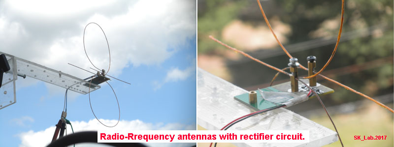
Сurrent, which is produced by the antenna, you will see on 100uA (700Ohms) head, connected directly to rectifier's output. The voltmeter is connected in parallel and shows the voltage drop (36mV) on the head. Not bad result on the picture below.

*** For reference, the schematic diagram of each antenna is the same and can be taken from this page. ***
Abnormal result.
If you have never been involved in collecting radio wave energy, then you will take the result as is. Otherwise, the received power may seem overestimated. Even for me, when I can repeat this experiment with the same result, the received power seems very large.
There is no magic or trick here. This
really works, just because there is a common place where the signal is
strong and the antenna design is correct for this particular case.
Level of signal at 750MHz.
The simplest thing is to check the signal level close to the antenna. This is done with a simple SDR radio.

It is clear that view of the computer screen is impossible, so two copies of the screen that we may be interested. The first is the signal level with SDR antenna connected. And the second level of noise, when the antenna is disconnected. In both cases, the RF gain is set to 0dB.


As usual, for all SDR radios, the signal is measured in dBFS, where 0 dBFS is the top signal level that can be measured & depends on the width of ADC converter (which is part of the radio).
If we jump over unnecessary details, then we have a +20dB to +30dB signal above the noise level. It's really a lot. For comparison, the signal level from the FM radio stations (88-108MHz) is +5dB to +10dB.
Antenna.
The antenna was designed as simply as possible. It is made of two pieces of wire with a diameter of 1 mm and a length of 630 mm each. Wires solder together at distances of 115 millimeters from the endings. The same points are used to connect to the rectifier.

The name of such an antenna can be assigned any, 'dual-loop' or so. In fact, this is a combination of two antennas: "Folded Dipole" and "'Half-Wave +' Dipole". The combination was chosen only to increase the internal resistance of the antenna. This, in the end, allows me to reduce the current and increase the output voltage delivered to rectifier.
This approach is important for me, since I do not use energy directly. I charge the capacitor bank at the beginning, and then, when the voltage is enough to start DC-DC converter, I get the power.
How much power?
This is probably the most difficult question. In order to get an idea of the available power, I use the time necessary to charge the capacitor bank. Usually these blocks from 0,036F to 0,09F.
For more details on how this happens, you can see here, but briefly, a similar installation allows me to charge a 0,036F capacitor from 0,06V to 0,5 Volts for 8 to 17 minutes.
Of course this is not very much power, only 0,0045J. But this is quite enough, for example, to light a white LED for 0,1 second (3V*0.01A*0.1sec.= 0.003Joule).
Improve the circuit ...
In many cases it is necessary to increase the power taken from the antenna. Perhaps you are lazy that would put the micro controller in the deep sleep mode (for MSP430 it is LPM_4), or your "off shelf" DC-DC converter has a relatively huge quiescent current & so on.
'Straight a head' solution - to increase the number of antennas along with set of rectifiers in each. You can arrange them at a wavelength distance from each other and this will work. But rectifier diodes, for these frequencies, are extremely overpriced at the moment, and this kills the idea.
Second - you can add a reflector on the distance 4-5 cm behind the antenna. This will complicate the antenna design and add weight. But in a number of cases this does not matter. In return, you can almost double the output voltage or increase power, from same setup, by about 1,5 times. As a disadvantage, the antenna will become more directional and tuning will become more critical.
For example, I can place this antenna on the front of my satellite dish and this will increase the output voltage from 0,5 - 0,7V to ~ 1.5V. In the case that the goal is to light the LED every 15 minutes, this voltage will be enough to start any DC-DC converter for solar garden lights, which were discussed here. Just add a delay circuit (capacitor + resistor to ON/OFF input).
The last, you can connect several antennas, by RF, to a single antenna array and use a one rectifier/multiplier for all. It's a good idea if you know how to do it. In practice, even for a good RF person, who knows what he doing (with all the necessary equipment) it can take weeks to complete the project. Doing same at home, will be more like a lottery game, with the same result in most cases.
To add complexity, I will say that even the diameter of the wire from which the antenna is made - matters. If
we increase the diameter of this wire, say from 1 mm to 1,5 mm, the antenna will
get "better", but this will lead to a decrease in the output voltage and
power in the same way. Only because it will not cover the entire frequency range (720 - 745MHz) from which the power is sucked :)
OK. I ran out of ideas. If you know how to improve this antenna, then let me know. My email is at the end of each page. Thanks in advance.
Only in case you decide to do something similar.
Harvesting power from radio waves is like fishing. That is, if "no fish in the lake", then you will not catch anything. Therefore, in order to make this idea to run, in your particular case, you need to:
a) find a 'hot spot' using any RF detector (this one working for me at the moment);
b) with any SDR Receiver find RF frequency with max. power (RTL-SDR cheep & good enough);
c) make a simple antenna (Dual-Loop or so), add RF rectifier and enjoy 'free' energy :)
a) find a 'hot spot' using any RF detector (this one working for me at the moment);
b) with any SDR Receiver find RF frequency with max. power (RTL-SDR cheep & good enough);
c) make a simple antenna (Dual-Loop or so), add RF rectifier and enjoy 'free' energy :)
Yes. It's all. It's simple like that.
1. A good article, about radio emission in London UK,( pdf): 'Ambient RF Energy Harvesting in Urban and Semi-Urban'.
2. Some practical data. In this case, this antenna charges a block of 0.036F capacitors. How long?
3. Harvesting power from radio waves. 750MHz, TV broadcasting. You are here at the moment :)